Mil logic device Logic combinational gates circuits using gate boolean algebra electronics circuit combination example three electrical full nand below these operators shown Understanding digital logic ics — part 1
Figure 2. Logic diagrams Device type 04 Circuit B
Logic gates circuit combinational experiment draw diagram guide online gate not input schematics sparkfun boolean clipart dic lab work learn
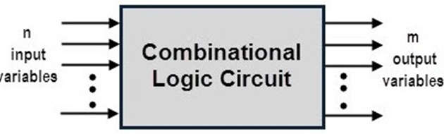
Combinational logic circuits using logic gates
And gate diagram transistorExamples of logic circuits Draw the logic circuit for following boolean expressionLogic gates circuits.
Not logic gate diagramLogic gates basic circuit integrated configuration ttl cmos symbols series using summary ieee standard Combinational logic circuits : classification and functionsLogic gates truth table and diagram.

Figure 2. logic diagrams device type 04 circuit b
Basic logic gatesPin on logic Ieee basic electrical symbolsPatent us8504963.
Figure (a)Circuit diagrams logic gates What is logic circuitIeee basic electrical symbols.

Integrated circuit logic diagram
Logic diagramLogic gates electronics symbol standards electronic projects simple Logic gates circuitsLogic gates circuits.
Logic binary decimal encoder deskripsiGadgets projects electronics Logic gateWhat is logic diagram and truth table?.

Logic diagram gates table truth circuit circuits excel gcse computer science computerscience
Combinational logic circuits : classification and functionsLogic diagram circuit truth table draw schematic our able Difference between combinational and sequential logic circuitIec electrical symbols pdf.
Boolean expression to logic circuit examplesLogicblocks experiment guide Figure (a) shows the ansi/ieee standard logic symbolsIeee ansi symbols logic electrical figure standard.
![[Solved] Develop a logic circuit necessary to meet the following](https://i2.wp.com/www.coursehero.com/qa/attachment/37094376/)
What is logic diagram and truth table?
Logic truth[solved] develop a logic circuit necessary to meet the following .
.